Creating a URDF from a CAD Model using OnShape
This tutorial covers the process of taking a robot CAD model and exporting it as a URDF (Unified Robot Description Format) file. You will learn what a URDF is, how to bring a SolidWorks assembly into OnShape, how to set up joints and links correctly, and how to export the final URDF. The steps use SolidWorks as the starting CAD tool and OnShape for the export pipeline, but the concepts apply to other CAD tools as well. By the end, you will have a URDF file ready to load into a simulator like Isaac Sim or Gazebo, or into a ROS 2 pipeline for real robot control.
Why OnShape for URDF Export?
OnShape is not the only way to generate a URDF from a CAD model. SolidWorks has the sw2urdf plugin, Fusion 360 has fusion2urdf, and FreeCAD has built-in support through its robot workbench. If you are already in one of those tools with a clean assembly, the native export is probably faster.
OnShape is worth considering when your CAD tool lacks a maintained exporter, or when your team uses a mix of tools and you want one consistent export pipeline. Being cloud-based, anyone on the team can open the assembly in a browser without installing SolidWorks or Fusion 360, which matters when a software engineer needs to check the joint structure but does not have a CAD license. The model lives in one place, so there is no confusion over which version of the file is current. Changes are visible to everyone immediately, and the export can be triggered from any machine without moving files around first. It is also free for public documents, so there is no license to manage, and the onshape-to-robot exporter is actively maintained and handles inertia and mesh export reliably. For teams using a mix of tools, both SolidWorks and Fusion 360 users can export to STEP and follow the same OnShape workflow from that point forward, rather than maintaining two separate export setups.
What is a URDF?
A URDF is an XML file that describes a robot’s physical structure. Simulators and robot software like ROS use it to understand how a robot is built, what parts it has, how they connect, and how they move relative to each other.
A URDF describes the robot as a tree of links and joints:
- Link: a rigid body such as a base plate, arm segment, or gripper finger. Each link has geometry (the mesh shape), mass, and inertia properties.
- Joint: the connection between two links. It defines how one link moves
relative to another. Common types are:
fixed— no motion, the two links are rigidly attachedrevolute— rotation about a single axis (e.g., a hinge or motor)prismatic— sliding along a single axis (e.g., a linear actuator)
- Parent/Child: joints connect a parent link to a child link. The whole
robot forms a tree starting from a single root, usually called
base_link.
A simple two-link arm would look like this in structure:
base_link
└── shoulder_joint (revolute)
    └── upper_arm_link
        └── elbow_joint (revolute)
            └── forearm_link
Inside the URDF file, a single joint looks like this:
<joint name="shoulder_joint" type="revolute">
  <parent link="base_link"/>
  <child link="upper_arm_link"/>
  <axis xyz="0 0 1"/>
  <limit lower="-1.57" upper="1.57" effort="10" velocity="1.0"/>
</joint>
The axis field defines which direction the joint rotates around. The limit
field sets the minimum and maximum angle in radians, along with effort and
velocity limits. Getting these values right is important for simulation — a
joint with wrong limits will either not move or move past its physical range.
Step 1: Prepare Your CAD Assembly
Before importing into OnShape, make sure your CAD assembly is clean and well-organized. This will save significant time during the joint assignment step. A messy assembly with undefined mates or floating parts will cause problems after import.
- Each moving part should be a separate component in the assembly
- Parts that move together as one rigid body should be grouped or mated as fixed in the CAD
- Suppress any cosmetic or non-structural parts such as bolts, labels, and fasteners that you do not need in simulation. These add unnecessary complexity to the URDF and slow down the simulator.
It is also worth sketching out your intended link tree on paper before starting. Knowing which parts form each link, and which joints connect them, makes the OnShape setup much faster.
Step 2: Import Your CAD File into OnShape
(Note that this is commmon to all CAD softwares. Solidworks is just chosen as an example)
OnShape supports two main import approaches for SolidWorks assemblies.
Option A: Import SolidWorks Files Directly
OnShape can import SolidWorks native files (.sldprt and .sldasm).
- Go to https://cad.onshape.com and log in
- Click Create in the top left corner
- Select Import
- Upload your
.sldasmfile along with all referenced.sldprtpart files - OnShape will convert the assembly and open it as a new document
Import all part files together with the assembly file in one upload. OnShape needs all referenced parts to reconstruct the assembly correctly. If you upload only the
.sldasmwithout the part files, parts will appear missing or as empty shells.
This approach preserves your existing SolidWorks mate structure, which saves time in the joint assignment step. However, it can sometimes produce broken references or missing geometry if the SolidWorks file uses external references or complex configurations.
Option B: Export as STEP and Import (Recommended)
A more reliable approach is to export your SolidWorks assembly as a STEP file
(.step or .stp) and import that into OnShape instead. STEP is a universal
CAD exchange format that OnShape handles cleanly without broken references.
To export from SolidWorks:
- Go to File > Save As
- Set the file type to STEP AP214 or STEP AP203
- Save the file
Then import into OnShape the same way — Create > Import > select the
.step file.
The tradeoff is that STEP files do not preserve mate or assembly structure. All parts will appear as independent bodies in OnShape, and you will need to manually group parts that belong to the same rigid link before assigning mates. For most robot assemblies this is straightforward since the grouping follows the physical structure of the robot.
Once imported, check that all parts appear correctly. Cosmetic issues like color or appearance can be ignored, but make sure no parts are missing. Rotate the model and inspect it from multiple angles.
OnShape may change the appearance of some parts during conversion. This does not affect the URDF export — only geometry and mate structure matter.
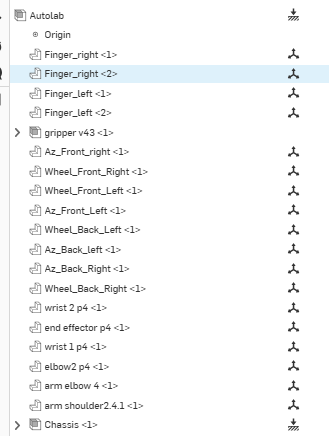
Step 3: Name Your Parts
The OnShape URDF exporter reads part names to build the link names in the
URDF. If your parts are named Part1, Part2, and so on, your URDF will be
very hard to read and debug.
In the parts list on the left panel:
- Rename each part to match the link name you want in the URDF
- Use underscores and no spaces (e.g.,
base_link,upper_arm,wrist_link) - Keep names short and descriptive
- Parts that will be combined into one rigid link can share a name or be merged before export
Step 4: Assign Joints Using Mates
In OnShape, joints in the URDF come from mates between parts. You need to define a mate for each joint in your robot.
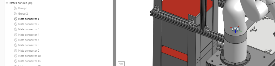
Mate Connectors
Before creating mates, you should define Mate Connectors on each part. A mate connector is a coordinate frame you place on a part to define exactly where and in what orientation a mate will be created. Think of it as marking the precise joint location on the geometry.
To add a mate connector:
- Right click on a part in the assembly
- Select Add mate connector (or just click on the mate connector button near the “Insert” button on the toolbar at the top)
- Place it at the center of the joint — for example, at the center of a rotating shaft or hinge pin
- Orient the Z axis of the connector to match the intended axis of rotation or translation. The Z axis of the mate connector becomes the joint axis in the URDF.
Taking time to place mate connectors accurately is worth it. A poorly placed connector will result in the wrong joint origin in the URDF, which causes the robot geometry to appear offset or rotated incorrectly in simulation.
The image below shows a mate connector in the figure as well as the menu on the left (highlighted)
Creating Mates
Once mate connectors are placed, create mates between them:
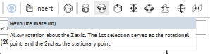
- For each joint, choose the correct mate type (look at the image above to see the place where the mates will be):
- Fastened mate becomes a
fixedjoint in the URDF - Revolute mate becomes a
revolutejoint - Slider mate becomes a
prismaticjoint
- Fastened mate becomes a
- Select the mate connector on the parent part and the mate connector on the child part
- Name each mate clearly (e.g.,
shoulder_revolute,elbow_revolute)
Every joint must connect exactly one parent part to one child part. The assembly must form a tree with no loops. If part A connects to part B and part B connects back to part A through a different mate, the URDF will be invalid.
The axis direction of the mate connector is particularly important. In the URDF, the joint axis is defined by the Z axis of the mate connector on the child part. If you orient the connector wrong in OnShape, the joint will rotate around the wrong direction in simulation. After creating each mate, animate it in OnShape to confirm the motion direction matches what you expect before moving on.
The image below shows OnShape mate dialog showing a revolute mate being defined between two mate connectors
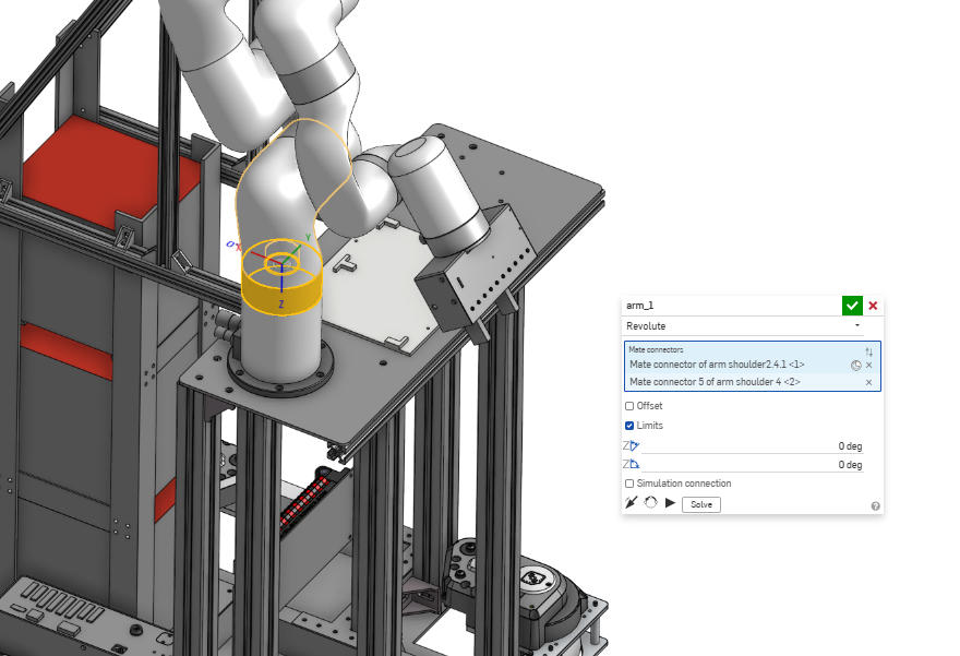
Setting Joint Limits
To set joint limits, click on the mate in the feature tree, open its properties, and enter the minimum and maximum angle or distance. The OnShape URDF exporter reads these directly and writes them into the URDF limit tag.
If you skip this step, the exported URDF will have no limits on those joints. In simulation this means the joint can rotate freely to any angle, which usually causes the robot to collapse or behave unrealistically.
Step 5: Export the URDF
Once your parts are named and all mates are defined, you can export the URDF directly from OnShape.
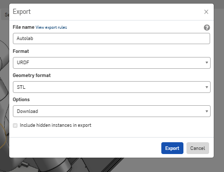
Right click on the file name in the tab bar at the bottom of the screen. Click Export. In the export dialog, select URDF as the target file format and then click Export. It will take a few minutes for the export to process and download depending on the complexity of your assembly.
This will generate a zip file containing:
robot.urdf— the URDF file describing your robot’s structure- A folder of mesh files (
.stlor.obj) for each link’s geometry
Extract the zip file and keep the mesh folder in the same directory as the URDF file. The URDF references the meshes using relative paths, so moving them apart will cause the robot geometry to not load.
Step 6: Validate the URDF
You can use online URDF viewers such as https://viewer.robotsfan.com/ to visually inspect the robot without needing a full simulator installed. Load the entire folder generated by the onshape (urdf and the meshes) and check that all links appear in the right positions and orientations.
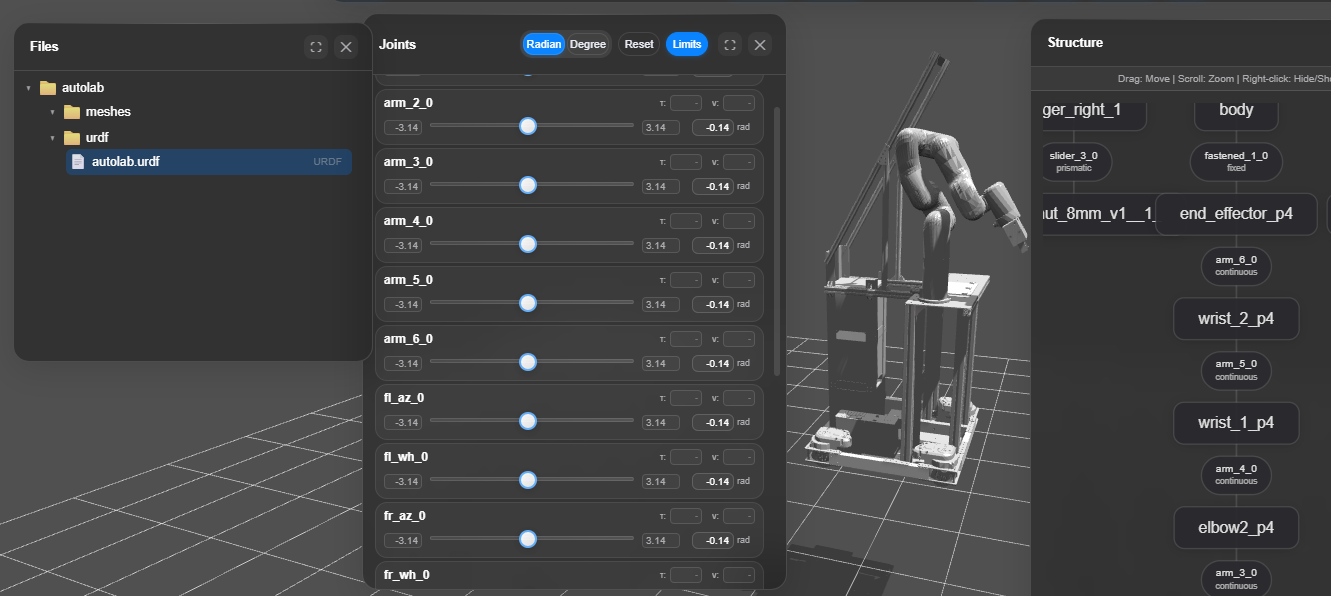
In the image below, you can see the entire folder (urdf + meshes loaded), which then generates the robot structure, the joint-link tree, etc. The viewer displays four key panels:
Files panel (left) — shows the loaded package with the meshes/ folder and urdf/autolab.urdf file, confirming the relative path structure is intact and the viewer resolved all references correctly.
3D Viewport (center) — renders the full robot geometry using the loaded meshes, allowing you to visually confirm that all links appear in the correct positions and orientations.
Joints panel (center) — lists every joint (arm_1_0 through arm_6_0) with interactive sliders so you can manually drive each joint and verify that motion direction and limits match your expectations.
Structure panel (right) — displays the full parent-child link tree, from arm_shoulder_4 at the base up through wrist_2_p4 at the tip, confirming the tree has no loops and the hierarchy exported correctly.
Common Issues and Fixes
Parts are missing after import into OnShape
Make sure you uploaded all .sldprt files together with the .sldasm file
in one import batch. OnShape cannot resolve external references if the part
files are missing.
Joints move in the wrong direction Flip the axis in the OnShape mate properties, re-export, and re-validate. You can also edit the axis line directly in the URDF file as a quicker fix.
Joint limits are wrong or missing Set limits in the mate properties in OnShape before exporting. The exporter reads them directly from the mate. If limits are missing the joint will be unconstrained in simulation.
Part masses are zero Assign a material to each part in OnShape so the exporter can compute mass from density. Alternatively, edit the inertial blocks in the URDF file manually after export.
check_urdf reports a loop Your assembly has a part connected to more than one parent. Find and remove the extra mate causing the loop.
Meshes do not appear in the simulator
Check that the mesh folder is in the same directory as the URDF. The URDF
uses relative paths like meshes/base_link.stl — if the mesh folder is
moved or renamed the simulator cannot find the geometry.
Opening Your URDF in Isaac Sim
- Enable the
isaacsim.asset.importer.urdfextension if not already active: Window > Extensions > search forisaacsim.asset.importer.urdfand enable it - Go to File > Import and select your
robot.urdffile - In the import settings:
- Set USD Output to your desired output location
- Check Static Base if your robot has a fixed base (e.g. a mounted arm)
- Enable Allow Self-Collision under the Colliders section
- Click Import — the robot will appear in the stage
Keep the
meshes/folder in the same directory as the.urdffile before importing, or Isaac Sim will not resolve the geometry paths correctly.
Summary
To generate a URDF from a SolidWorks CAD model: clean up your assembly, import it into OnShape, rename parts to match your intended link names, assign mates for each joint with correct axis directions and limits, then export as URDF. Validate the output with check_urdf or an online viewer before using it in a simulator or ROS package. Getting the assembly structure and mate setup right before export avoids most common errors downstream.
See Also
Further Reading
- URDF XML specification: http://wiki.ros.org/urdf/XML
- OnShape Learning Center: https://learn.onshape.com
- Online URDF Viewer: https://myrobotics.eu/urdftools/viewer/
References
- Open Robotics, “URDF XML Specification,” ROS Wiki, 2021. [Online]. Available: http://wiki.ros.org/urdf/XML
- OnShape, “Importing and Exporting Files,” OnShape Help, 2024. [Online]. Available: https://cad.onshape.com/help