3D Printers
This article is a technology overview of the fundamentals of 3D Printers, especially “Fused Filament Modeling” (FFM) & “Fused Deposition Modeling” (FDM). It explains the fundamentals of 3D Printer technology and applications. It should be useful for those considering working with, designing, or modifying a 3D printer. It is not intended to be a guide for using the lab’s 3D printers.
The Basics
What is 3D printing?
Fundamentally, 3D Printing is the concept of additively producing a physical part from a 3D part file. Typically, this done by breaking a 3D part into horizontal layers and then printing each layer as a planar part of constant thickness. However, there are other methods. For example, Carbon3D, uses an alternative approach known as Digital Light Synthesis which is a two step process of printing with a support resin then melting the support structure away.
Recently 3D printing has become somewhat of a revolution for three reasons:
1) Fast, Easy, Prototyping 3D printing is often able to produce prototype parts faster and easier than traditional manufacturing methods. In theory, 3D printers can work similarly to a traditional paper in which a user ‘presses print’ and returns some time later to extract a completed part from the printer.
2) Parts which are otherwise unattainable 3D printing enables manufacture of parts which are impossible (or extremely difficult) by traditional methods. Complex internal geometries for example which are often impossible to make by traditional machining can easily be produced by 3D printing. This can be especially helpful for parts which require internal fluid .
3) No cost for complexity: Unlike traditional machining, 3D printed parts often incur no additional costs when part complexity is increased. Ribs, gussets, fillets, chamfers, internal geometries, etc all typically add additional steps to a traditional machining process, but require no additional overhead for 3D printing. This can free part designers to create more complex parts and spend less time on Design for Manufacture (DFM).
Different types of 3D printing
3D printing comes in many flavors. Varying requirements for precision, materials, speed, cost, size, and application have produced a wide range of different 3D printing technologies. A brief summary of some of the most common variations is as follows. A more detailed explanation is available here.
Fused Deposition Modeling/Fused Filament Modeling (FDM/FFM)
When makers, hobbyists, and small companies discuss 3D printing they are almost exclusively referring to FDM/FFM. Makergear, Makerbot, RepRaps, Lulzbot, DeltaWasps, FlashForge, Ulitmaker, Witbox, and Craftbot, are all common examples of FDM/FFM printers.
FDM works by melting a plastic filament, which is then extruded through a nozzle and deposited onto a build surface layer by layer to produce a three dimensional part.
The acronym ‘FDM’ is trademarked by Stratasys, one of the largest player in the 3D printing industry. Other 3D printer companies using this type of technology generally refer to it by a similar acronym although the technology is generally identical.
Selective Laser Sintering (SLS)
Within larger engineering companies, SLS machines are sometimes available. These use high powered lasers to fuse together extremely fine metal powders in an oxygen-reduced environment. The reduced oxygen environment is essential to prevent oxides from forming which can inhibit the bonding of powder.
SLS printing is extremely expensive both in terms of capital equipment (millions) and feedstock. Trained operators are required to safely operate the machines as the fine metallic powder produces a serious inhalation hazard. The technology can however produce extremely complex parts out of difficult to machine materials such as titanium and stainless steel. CMU has a few of these printers on campus, including one that students can send parts to in the Mechanical Engineering Shop.
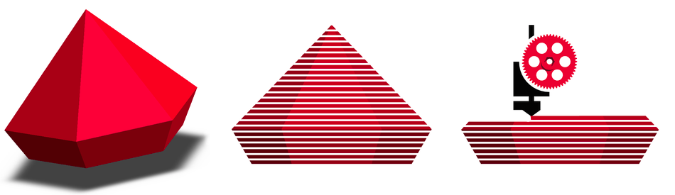
Stereolithography (SLA)
Stereolithography is an older technology that has made significant headway and gained more commercial adoption within the last 10 years. The process is based on using a vat of liquid photopolymer material, which hardens when exposed to certain wavelengths of light. To form a part a build plate is positioned within the vat onto which a layer of the part is projected in the correct wavelength. After being exposed for several seconds, the build plate moves by a layer thickness and the next layer is projected onto the surface of the first. A good video of the process is available here.
There are two primary variants of the stereolithography; top down and bottom up. In top down approaches the build plate is initially positioned just below the surface of the liquid in the vat. In bottom up approaches the build plate starts at the bottom of the vat and the image is projected through a plate of glass on the bottom.
Typically, SLA machines also are operated with secondary equipment which further harden and/or clean the product after it is removed from the vat. SLA feedstocks prices vary significantly across companies and materials but an extremely wide range of polymers with vastly different mechanical properties are available.
SLA is known for producing parts with high quality surface finishes at a low price, albeit higher than FDM/FFM cost. It is common to encounter SLA machines (or proprietary variants of it) within medium-to-large engineering companies, although low cost desktop versions have begun to gain traction (i.e. FormLabs).
SLA has also spawned some interesting variants recently. The most notable is Carbon3D which combines bottom up SLA printing with an oxygen permeable print window on the bottom of the vat. The oxygen permeability reduces the curing speed of the material and thus changes from a ‘layer by layer’ paradigm to a ‘continuous’ print where a video is projected onto the material while the build platform slowly and continuously moves upward. An example can be seen here.
Material Jetting
Material Jetting is a process which can be visualized similar to an inkjet printer. A print head moves across a build surface while hundreds of nozzles deposit micro-droplets of a liquid polymer material. These droplets then harden (usually via photo-curing) to form the geometry of the part. After traveling across the print surface, the nozzle (or the build platform) moves by one layer thickness and the process repeats.
The Stratysis Objet Series of printers is a commonly encountered material jetting machine. Objet machines are accessible to students in CMU’s Material Science Shop run by Larry Hayhurst and in the School of Architecture dFab lab
Material jetting machines are known to produce parts with good surface finishes (tolerances of .005 inches are achievable) and are capable of printing multi-material parts. Material jetting machines typically use a support material to support internal surfaces and provide a consistent surface finish. Because of this a huge amount of material is often needed to print even simple parts, as they are typically enclosed in around 1/8” of support material.
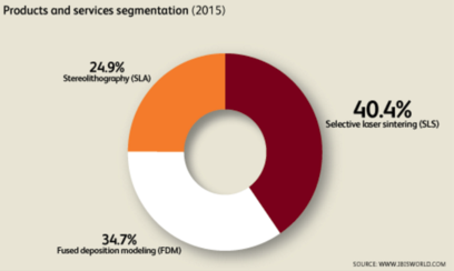
Industry Segmentation
IBISWorld provides a overview of the 3D printer manufacturing industry. This is focused on large high volume companies such as Straysis and 3D Systems and does not include many of the effects of smaller volume ‘maker’ targeted companies. It shows a roughly equal breakdown between SLA, SLS, and FDM technologies.
How does a FDM/FFM 3D printer work?
Parts of an FDM/FFM 3D printer
Hot End
Broadly referred to as the ‘nozzle’ the hot end is the portion of the 3D printer which melts, shapes, and deposits print filament to form the part. Typically it is made of the following components:
Nozzle
The nozzle is typically made of brass and is a conical nozzle with a small diameter hole through it. For low-cost machines (i.e. anything ‘maker’) it is usually attached to the heat block with a M6x1 thread. It is designed to be heat-conductive to maintain melting temperatures at the tip of the nozzle where small geometry limits the amount of thermal energy that can be transferred to the material. The length of the small diameter hole is often minimized as viscous friction affects become significant and require a large extrusion pressure to push the highly viscous molten plastic through a small port.
Heat Block
The heat block is generally made from aluminum (sometimes brass, i.e. ultimaker) and is responsible from transferring heat from the heater (usually a cartridge heater) and thermistor. It typically connects to both the nozzle and barrel with a single M6x1 thread. Strangely, no one seems to use a tapered thread which often leads to molten plastic leaking out from the top and bottom of the heatblock. Teflon tape helps, but a worthwhile project would be to replace this with a NPT thread or similar.
Barrel
The barrel is a tube (usually stainless steel, often with a PTFE liner) which connects the heat block to the extruder (possibly through a Bowden tube). The main design challenge of the barrel is to reduce the amount of heat which can travel across it, thus confining the melt zone to the heatblock/nozzle assembly. Too much heat traveling up the barrel leads to softening/melting of the filament which leads to jamming, excessive extrusion, and inconsistent prints. Barrels are typically made from stainless steel due to its low thermal conductivity. A PTFE liner also is commonly used since it can withstand the high temperatures at the nozzle, provides good thermal insulation between the filament and the metallic barrel, and perhaps most importantly molten filament will not stick to it’s slippery surface.
Numerous barrel designs are available, with different features to try to limit heat transfer. Heat sinking features (such as aluminum fins) are common, as are ‘heat brakes’ which is a section of narrow diameter to reduce the cross-sectional area through which heat can transfer. These different features can have a significant affect on the performance of a 3D printer and thus it is recommended some experimentation be performed if working on a 3D printer project and print quality is sub-optimal. Some examples are RepRap, CycleMore, and a larger RepRap.
Extruder/Filament Drive
The extruder/filament drive component is the mechanical assembly used to push the feedstock filament through the system. It typically features a stepper motor, some sort of gear reduction, and a ‘drive gear’ which engages with the filament to push it through the system. Feeding the filament requires large forces and thus significant design effort is applied towards the drive gear (making it firmly engage with the filament, not tear it) and the filament support to prevent it from buckling. There are numerous different extruder designs, some of which are must better suited for certain filament types than others (i.e. soft vs. hard filaments).
Many of the extruder designs can be 3D printed, so once you have one that at least partially works, it is easy to try numerous other designs and to make modifications.
Some of the most commonly used extruder drives:
- Wade’s Geared Extruder - One of the first reliable extruder designs.
- Frequently used on reprap projects, Greg’s Hinged Extruder, is a variant on the Wade extruder, which is similar to the design used on many commercial printers such as MakerGear and MakerBot.
- Ultimaker extuder, one of the best extruders for common PLA/ABS filament. Has a large gap between the drive gear and output tube thus making it less suitable for soft filaments (i.e. ninjaflex, semiflex).
X-Y axes
The x-y axis construction of 3D printers is one of the most variable aspects between different designs. Within the ‘traditional approaches’ (in which there is one motor per axis) different printer manufactures chose to move the nozzle, print bed, or both. Drive mechanisms vary between rack gear drives, belt drives, and filament drives.
A number of clever alternative designs also exist which couple the motion between different motors to move the print bed or nozzle. The CoreXY design mixes motion from two motors for the X-Y axes through a single filament or belt drive. Delta geometries mix motions between 3 vertical axes to produce coupled x-y-z movements transferred to the nozzle via connecting rods with ball joints. Proponents of these technologies argue that they provide more symmetric construction, reduced moving mass (enabling higher print speeds), and larger or more practical build volumes. Opponents cite increased mechanical complexity, increased software complexity, and varying positional tolerances throughout the build volume.
Z axis
The z axis is responsible for moving the build platform (or occasionally the nozzle) between layers. As such, it has significantly different requirements than the X-Y axes which are continuously rapidly moving throughout the print. Z axes are typically geared lower since speed is less critical but they must support a much larger mass. Backlash is also less of a design consideration since the axis typically only moves in one direction throughout the print.
Endstops
Since almost all 3D printer designs utilize stepper motors for axis motions, inclusion of endstops is necessary for homing the axes at power up. The importance of good endstop design should not be overlooked since its accuracy and repeatability will directly affect the quality of the print. The ability to provide mechanical adjustment is often essential as printer geometry will be varied via the use of different nozzles, barrels, extruders, etc.
Wiring and firmware must also be considered, since it is often desirable to have the endstops ‘always active’ so that they will prevent any of the axes trying to drive beyond it’s mechanical limits, which can be caused by incorrectly generated G-Codes. Use of interrupt driven code for endstop checking is best for this application, since response time is critical and the processors in 3D printers are typically heavily taxed performing geometry calculations.
Build Platform + Build Chamber
The platform on which the part to be built is worth consideration. These are typically heated to increase material adhesion, and the temperature may be varied throughout the print to maximize platform adhesion in the beginning of the print, and prevent thermal warping of the part in later stages. Surface material is important since it also greatly affects the adhesion. Glass is commonly used since it provides a low cost extremely flat surface, but it is often modified (with kapton tape, spray adhesives, etc) to improve adhesion. Professional-grade 3D printers (i.e. Stratysis) typically use various thermoplastics for their platform which can be rapidly swapped between builds. An interesting concept which has gained some traction is flexible build platforms. When placed on a flat surface they provide a flat surface for part construction, but then allow easy part removal by flexing the platform after the print is finished. This video highlights the concept well.
The RepRap Wiki has a great and exhaustive description of platform types and design considerations
Many printers (i.e. makerBot) also use heated build chambers. The concept is to prevent part warpage by maintaining a consistent temperature throughout the entire build volume. Often these chambers are heated by the build platform, with the entire build volume enclosed by an insulating chamber.
Fans
Fans are used extensively in 3D printers. They are commonly used for cooling the print material as it is deposited, cooling the barrel/hot-end assembly to prevent heat from melting the filament prematurely, and for cooling the stepper motor drivers. For the part-cooling fans, numerous control strategies are used including not running the fan for the initial layers (to maximize platform adhesion) or only running the fan when bridging gaps within the print.