Interfacing with the Nvidia Orin
This article will cover broad information necessary to use the Nvidia Jetson AGX Orin as your onboard compute platform. The aim is to provide a quick introduction to this popular edge compute option in robotics. We will go over important power considerations, how to interface your sensors with the Orin, and debugging tools for debugging connections and sensors to ensure reliable performance.
Table of Contents
- Table of Contents
- Power rails
- 40 Pin Expansion Connector (J30)
- High-Speed Interfaces and USB Architecture
- Debugging IO Connections
- Conclusion
Power rails
The Orin has multiple internal power lines derived from the 19V input from the barrel jack. Below is the image of the power delivery on the developer kit carrier board. The main power lines you may use are the 5V line and the 3.3V line.
It is important to always check the total current draw of all the peripherals connected to the power rail to ensure you do not exceed max current draw. For example, the USB ports are connected to the 5V power line and would be powering certain devices. If you try and power on something large from the 5V pin on the J30, you can exceed maximum current draw in some conditions.
It is highly recommended to have an external power supply for sensors like Lidars.
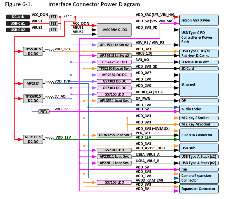
For more detailed information, look at the developer carrier kit documentation: Jetson AGX Orin Developer Kit Carrier Board Documentation
40 Pin Expansion Connector (J30)
The 40-Pin header provides access to many GPIO pins that can be used to interface (read/write) with sensors such as IMUs, Lidars, and encoders.
Below is the pinout for the 40 pin header, these can be used for interfacing with sensors and devices that don’t require fast processing and have low power requirements.
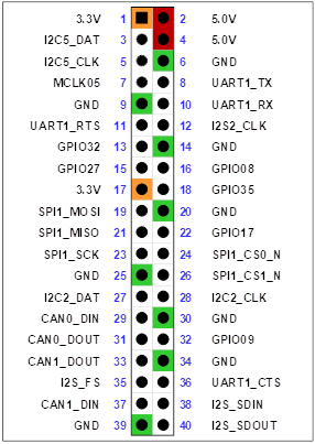
- Power Pins:
- 3.3V (Pin 1 and 17)
- 5V (pin 2 and 4)
- Multiple ground pins
Always ensure a common ground between Jetson and peripherals.
- GPIOs:
- Configurable general-purpose I/O pins.
- Very helpful for setting data to specific registers on drivers allowing configuration of sensors.
Always refer to the sensor datasheet to ensure you meet conditions for interfacing with the sensor. For example, adhering to the timing diagram.
There are other pins that support the communication protocol that you may want to use (UART, SPI, I2C, CAN). Different Embedded Communication Protocols
Important: All signal pins operate at 3.3 V logic levels and are not 5V-tolerant. This means trying to read a High (5V) pulse can damage the pin permanently. Use level shifters when interfacing with 5V devices. Level Shifters
High-Speed Interfaces and USB Architecture
Let’s take a look at the high-speed interface ports that one might use to interface with relevant sensors like cameras, flight controllers, LiDars.
USB Ports:
- 4× USB 3.2 Type-A Ports:
- Two ports at USB 3.2 Gen2 (10 Gbps) (J24 stacked pair).
- Two ports at USB 3.2 Gen1 (5 Gbps) (J33 stacked pair).
- All backward-compatible with USB 2.0.
- VBUS supports up to 2A for each stacked pair (shared between the two connectors in the stack).
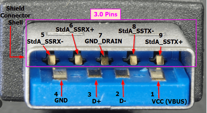
- As seem below, it is important to know the physical differences between the USB 3.0 and 2.0 cables. When using sensors with custom breakout boards, ensure that 3.0 pins (Tx+, Tx-, Rx+, Rx-) are exposed in order to interface with the sensor using 3.0 protocol.
- 2× USB Type-C Ports:
- Two Type C ports (J39 and J40)
- VBUS supports up to 5A on each Type C port.
- 1× Micro-USB (Micro-B) Port:
- Used for flashing, serial console access, and device mode operations.
Important: USB C ports are directly connected to the Orin SoC (dedicated UPHY Lanes), while USB A are connected via onboard hubs (share a single UPHY Lane). This means the bandwidth is shared across all connected USB A ports. For maximum performance (e.g., USB cameras), prefer direct USB 3.2 ports (Type C) when possible.
Networking:
- 1× 10 Gigabit Ethernet Port.
- Suitable for connecting high-bandwidth sensors like LiDars
- Supports 1Gb, 2.5Gb 5Gb, and 10Gb modes.
Debugging IO Connections
There are some tools to test the connections of your peripheral devices with the Orin. Here, we can look at dmesg, lsusb, and checking /dev/.
-
dmesgallows you to read kernel messages which include messages for hardware events like connecting a USB device. Here you can ascertain if the device is recognized, check vendor IDs, see what driver is asigned to interface with the device, and any errors that might have occured (not enough power, failing to recognize device, etc.) -
lsusblists all the USB devices connected to the system, and here you can find information on what bus the devices are on and what is their bandwidth. You can use verbose and tree tags to get more information. -
Finally,
/dev/contains device files that are created by theudevsystem. These files are created when the kernel detects and initializes the hardware. If file is not present in/dev/, look into damaged wires, pins, low power, not recognized by driver, and other such issues.
Important: When the Orin boots up, the power rails provide power to the sensors, which may boot up before the Orin and attempt communication. This can lead to sensors being in unknown states and behavior that is very hard to debug. Power sequencing is heavily recommended to ensure reliable bringup of sensors every time. A simple way to power sequence is using a MOSFET switch that enables power to the sensor given an input signal (which can be provided by the Orin after boot).
Conclusion
Hopefully, this provides you enough information about the NVIDIA Jetson AGX Orin and the Developer Kit Carrier Board that interfaces the peripherals with the SoC. Now you should be able to make the best design choices for connecting multiple sensors and actuators to the Orin with important considerations such as power, bandwidth, communication protocols, and different logic levels.