ROS Navigation
Dealing With Transforms
Setting up the ROS navigation stack on a robot that is not officially supported by ROS/3rd party is little bit tricky and can be time consuming. The robot setup guide is informative and helpful but can be confusing to many simply because it goes over a variety of steps. After a while, people may end up just following the lines without actually understanding the underlying reasons. This post tries to complement the information available on the ROS wiki and elsewhere to provide a better understanding of the components of navigation stack for a custom built robot.
It is easy to follow the ROS wiki on setup and configuration of the navigation stack on a robot. This series of posts outline the procedure with in-place reference to the ROS wiki and complementary information to help one better understand the process. The following post is the first one in the series which deals with the coordinate transform setup process.
Setup the coordinate transform tree for the robot
This involves defining the physical coordinate transform between different high-level components of the robot. This could be the transform between the coordinate axis of the base of the robot and the LIDAR and/or Kinect and/or the IMU and/or etc. depending on the sensors present on the robot. Once the tf tree is defined, converting a point represented in one coordinate frame into any other coordinate frame present in the tree will be taken care by ROS libraries. For example, the position of an object can be obtained from the RGB-D data from the kinect. To command a manipulator to grasp the object, the position of the object has to be converted to the manipulator’s frame of reference. If these transforms are defined in the tf tree, we can get the transformed point with a few lines of code. The following C++ code snippet illustrates how to get the transformed point.
geometry_msgs::PointStamped pt_to_be_transformed;
geometry_msgs::PointStamped transformed_pt;
pt_to_be_transformed.header = kinectPtCloud->header;
pt_to_be_transformed.point.x = kinectPtCloud->points[1].x;
pt_to_be_transformed.point.y = kinectPtCloud->points[1].y;
pt_to_be_transformed.point.z = kinectPtCloud->points[1].z;

tf::TransformListener manipulator_IK_goal_listener;
manipulator_IK_goal_listener.transformPoint("target_frame", pt_to_be_transformed, transformed_pt);
Follow the transform configuration guide to setup the coordinate frames and the transform trees. The guide should be straight forward to understand and follow. What the guide does not tell us is what to do when things go wrong. When dealing with custom robots, quite often the set up will be different from the standard wiki setups and guides but the procedure should be the same. Once the tf tree is defined, we can debug or figure out most of the problems by looking at the transform configuration tree. The coordinate transform tree can be visualized by using the following command:
rosrun tf view_frames
This will generate a file ‘frames.pdf’ in the current directory which will contain information about the existing coordinate frames, the links between two frames, their publishing frequencies etc.
Debugging example
An example tf tree with a robot setup with a laser scanner that uses hector mapping for scan matching and visual odometry is shown in the figure below.
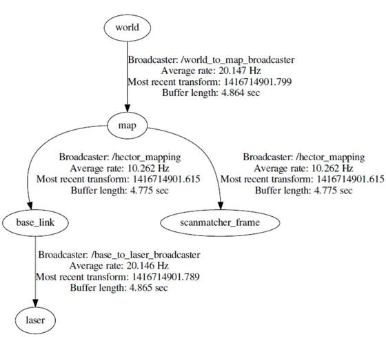
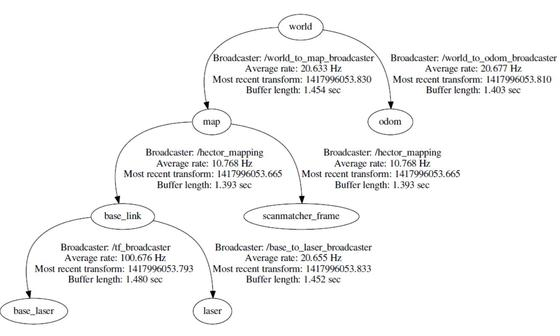
If someone is expecting their robot to navigate with the above tf configuration, they will have a hard time seeing anything move. As you can guess from the above coordinate transform tree, the tf tree is not complete. The path planner will be happy with the above configuration because it can get the laser scan matching at /laser with respect to the world coordinate frame but the robot base will not be able to command the wheel actuators. The error can be fixed by adding the transform between the world coordinate frame and the wheel odometry frame of the robot and the resulting tf tree is shown below:
Other useful tf tools for debugging are tf_echo and tf_monitor
Additional Notes on Transforms
Refer to the tf setup page on ROS wiki for code samples to write a transform publisher and a transform listener. Do note that it is not necessary to write dedicated nodes for publishing/listening to transforms. A transform can be published or subscribed from any ROS node. Another point to be noted is that, when you are using an URDF (for describing your sensor, manipulator etc.) the robot_state_publisher will publish the transforms from the URDF and therefore there is no need to publish the transforms separately. The robot_state_publisher reads the description of the robot from the URDF (which specifies the kinematics), listens to the state of the joints/frames and computes the transforms for all the frames.
If the robot has no movable fixtures/sensors/devices (for example is the Kinect/LIDAR is fixed on the robot without any actuation) then, the static_transform_publisher node can be used to define the transformation between these immovable fixtures/sensors/devices to a fixed frame on the robot (usually the robot base). A static transform can be easily setup from the command line using the following line:
rosrun tf2 static_transform_publisher x y z yaw pitch roll frame_id child_frame_id period(milliseconds)
Choosing the right Localization and Mapping Tools
After setting up the tf tree, sensor sources and the odometry information for your robot, the next step is to implement localization algorithms/mapping algorithms or Simultaneous Localization and Mapping(SLAM) algorithms. Although quite a few packages exist on the ROS repository, people often get confused on what to use for their robot. This post tries to provide you with some information that will complement the information present on the ROS wiki pages to help you choose the right set of algorithms/packages.
If you have tried at least once to look at the navigation stack in ROS, you must be aware of Gmapping, Hector mapping, robot_pose_ekf, robot_localization and AMCL. Let us quickly look at when to use these packages and what each one of them require.
- Gmapping:
- When to use this?
- Use this SLAM algorithm/package if you want to create a floor plan/ occupancy grid map using laser scans and pose information of the robot. Note that this algorithm can create only a 2D occupancy grid map. It should be sufficient for any ground robot that always navigates on a given plane. - What does it require?
- It requires
sensor_msgs/LaserScantopic ( laser scan source) and thetf/tfMessagetopic (pose of the robot) to be published.
- Adaptive Monte Carlo Localization (AMCL):
- When to use this?
- As the name suggests, this algorithm provides localization for your robot. It is a particle filter based probabilistic localization algorithm which estimates the pose of a robot against a known given map.Yes, AMCl requires a map to start with. In a nutshell, AMCL tries to compensate for the drift in the odometry information by estimating the robot’s pose with respect to the static map. - What does it require?
- It requires
nav_msgs/OccupancyGrid(map) ,sensor_msgs/LaserScantopic ( laser scan source),tf/tfMessagetopic (pose of the robot) and thegeometry_msgs/PoseWithCovarianceStamped(initial pose of the robot) to be published.
- Robot_pose_EKF:
- When to use this?
- If you have different sensors that can measure the position/velocity of the robot, for example if you have IMU, wheel encoders and a visual sensor all of which can provide the odometry information of the robot, you can use this package to fuse all the odometry information along with the dynamic model of the robot to produce a single odometry source which is more reliable that any of the individual source of information on its own. As you all can guess, it is essential a Kalman filter which uses the robot’s motion model along with the measurements/observations to provide a better estimate of the robot’s pose (position and orientation).
- Note that the output of this package on
robot_pose_ekf/odomorrobot_pose_ekf/odom_combinedgives only the 6D pose of the robot and not velocity. - What does it require? - It requires
nav_msgs/Odometry(x,y,theta from the wheel encoders),sensor_msgs/Imu(3D orientation from the IMU. Roll & Pitch are absolute values with respect to the world frame and the Yaw value is the angle of the robot base frame with respect to the world frame) and thenav_msgs/Odometry(visual odometry providing the 3D pose).
- Robot_Localization:
- When to use this?
- Use this when
robot_pose_ekfis not enough for your robot! This package offers all the goodness of robot_pose_ekf and more. It provides non-linear state estimation using the Extended Kalman Filter (EKF) and the Unscented Kalman Filter (UKF) to fuse information from arbitrary number of sensors. It also providesnavsat_transform_nodewhich helps in integrating GPS data (fixes) for the robot’s localization. The following picture from the Wiki is informative: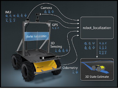 - What does it require?
 - It requires
/odometry/filteredtopic of typenav_msgs/Odometry,/imu/datatopic of typesensor_msgs/Imuand the/gps/fixtopic of typesensor_msgs/NavSatFix
Additional Considerations
For Gmapping, AMCL, and Robot_Pose_EKF:
- All the three sources of information are not required at every instance of fusion. This means that the sensor information can all arrive at different rates and it is okay if some measurements are lost. For the package to work, apart from the IMU measurements, either the wheel encoder measurements or visual odometry measurements should be present.
- With every sensor source, a covariance (uncertainty) value has to be supplied. Since the wheel encoders can only measure x,y and the theta (2D pose) it’s covariance values for the other values of the 3D pose (z, roll, pitch) should be set to a very high value as it does not measure them. For Robot_Localization:
- There is no restrictions on the number of the sensor sources. It even works with redundant sensor information like multiple IMUs and multiple odometry information.
- Ability to discard a particular sensor’s measurements in software on a case by case basis.
- Similar to the robot_pose_ekf package and as with any Kalman filter based pose estimators, covariance estimates in the form of
geometry_msgs/PoseWithCovarianceStamped, orgeometry_msgs/TwistWithCovarianceStampedmessages should also be made available along with the sensor information.