Basic Arduino Components
Arduino is a widely used platform in robotics and electronics due to its ease of use, affordability, and the wide variety of compatible components. Whether you’re building a simple circuit or a complex robot, understanding how to use basic components like LEDs, push buttons, potentiometers, buzzers, servos, and stepper motors is essential. This guide will cover these fundamental Arduino components, explain their functionality, and provide simple examples to get you started to where you can incorporate them in to future robotic projects.
LEDs
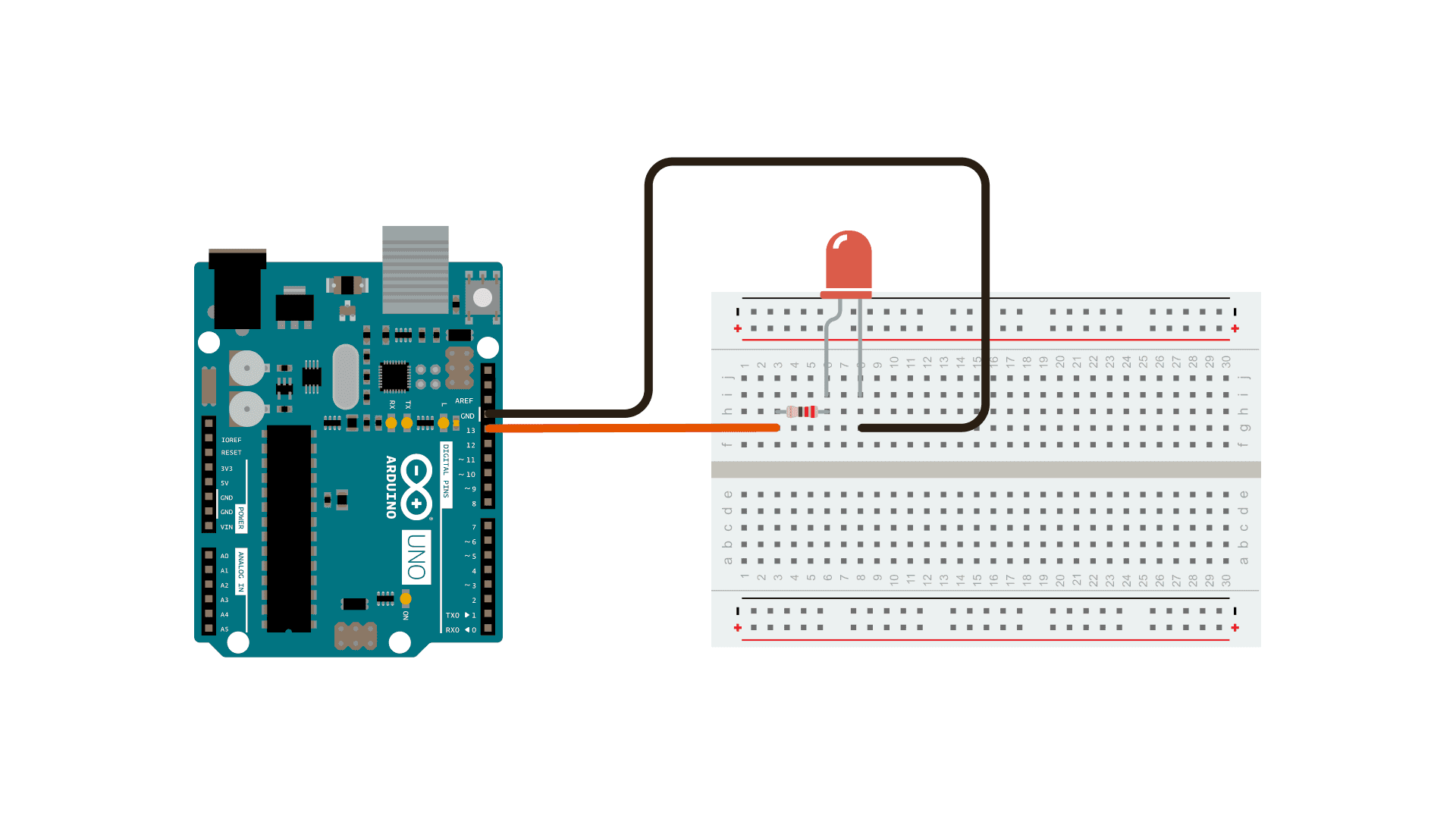
An LED (Light Emitting Diode) is one of the simplest and most commonly used components in Arduino projects. LEDs provide visual feedback and are often used as indicators for status, power, or signals. LEDs work by emitting light when an electric current flows through them in the correct direction. They require a resistor in series to prevent excessive current, which could damage the LED. To wire an LED to an Arduino, connect the long leg (anode) of the LED to a digital pin on the Arduino. The short leg (cathode) should be connected to the ground through a resistor, typically 220 ohms, to limit the current.
A simple wiring setup for an LED can be seen below along with a code snippet. The code will cause the LED to blink on and off.
// the setup function runs once when you press reset or power the board
void setup() {
  // initialize digital pin LED_BUILTIN as an output.
  pinMode(LED_BUILTIN, OUTPUT);
}

// the loop function runs over and over again forever
void loop() {
  digitalWrite(LED_BUILTIN, HIGH);  // turn the LED on (HIGH is the voltage level)
  delay(1000);                      // wait for a second
  digitalWrite(LED_BUILTIN, LOW);   // turn the LED off by making the voltage LOW
  delay(1000);                      // wait for a second
}
Blink Tutorial: This official Arduino tutorial provides a step-by-step guide to creating a simple blinking LED circuit. It covers the basic wiring and programming needed to control an LED, making it an excellent resource for beginners starting with Arduino.
Push Button
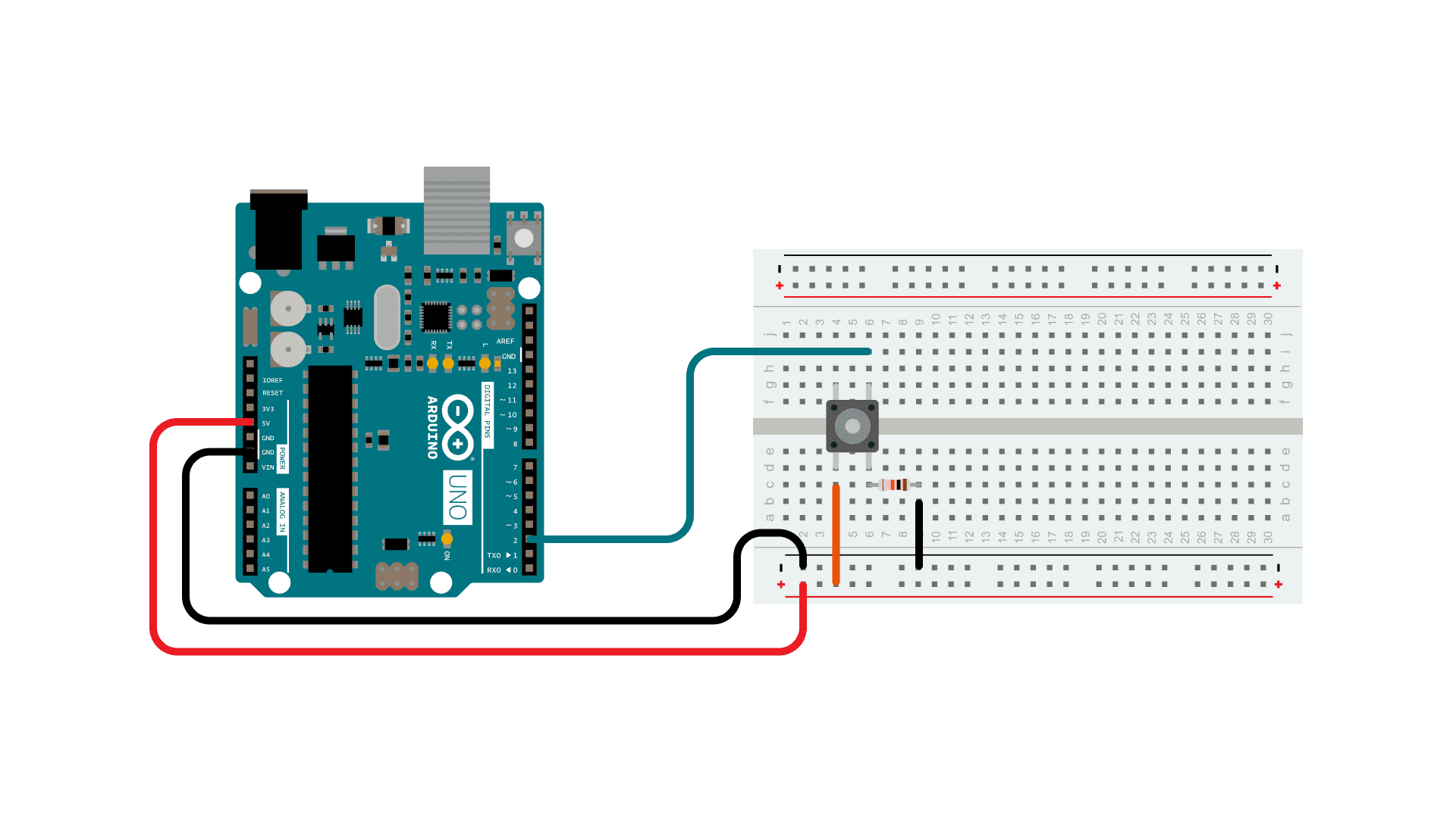
A push button is a simple input device that completes an electrical circuit when pressed. It is commonly used to trigger events or control devices in Arduino projects. When the button is pressed, it allows current to flow, sending a signal to the Arduino. When released, the circuit is open, and no signal is sent. Pull-down or pull-up resistors are often used to ensure the circuit has a defined state (HIGH or LOW) when the button is not pressed. To connect a push button to an Arduino, attach one leg of the button to a digital input pin and the other to the ground. Additionally, use a pull-up resistor or enable the Arduino’s internal pull-up resistor to stabilize the input state.
A simple wiring setup for a push button can be seen below along with a code snippet. The code will cause the serial monitor to print “Button Pressed” when the button is pressed, and print “Not Pressed” when the button is not pressed.
const int buttonPin = 2;  // the number of the pushbutton pin

// variables will change:
int buttonState = 0;  // variable for reading the pushbutton status

void setup() {
  // initialize the pushbutton pin as an input:
  pinMode(buttonPin, INPUT);
  Serial.begin(9600); // Start serial communication
}

void loop() {
  // read the state of the pushbutton value:
  buttonState = digitalRead(buttonPin);

  // check if the pushbutton is pressed. If it is, the buttonState is HIGH:
  if (buttonState == HIGH) {
    Serial.println("Button Pressed");
  } else {
    Serial.println("Not Pressed");
  }
}
Note: When a push button is pressed, it may generate multiple rapid on/off signals due to the mechanical nature of the button. This is known as “bouncing” and can cause unexpected behavior in your circuit. To address this, you can use a small delay in your code or implement software debouncing techniques. You can read more about debouncing here.
Button Tutorial: This link provides a more thorough overview of pushbuttons in Arduino and can be used to help clarify information about Arduino pushbuttons.
Potentiometers
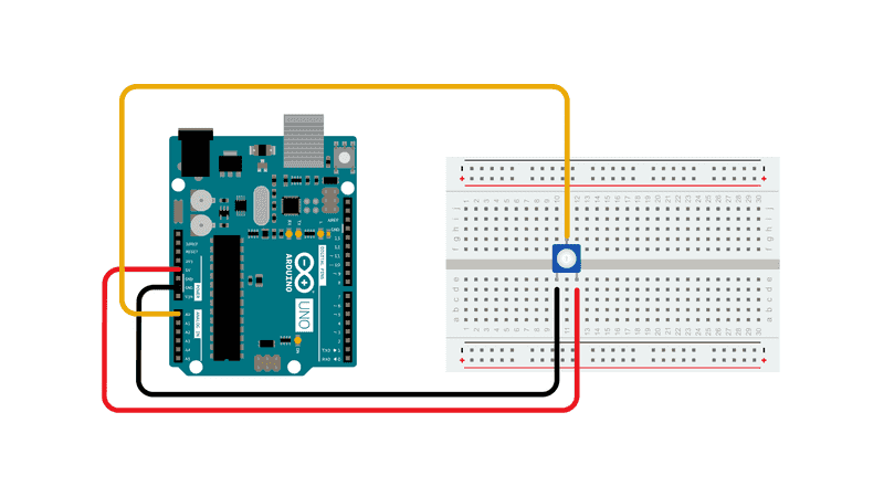
A potentiometer is a variable resistor that allows you to adjust resistance by turning a knob or sliding a lever. It is commonly used as an input device for controlling brightness, volume, or speed in Arduino projects. A potentiometer has three terminals: two outer terminals connected to a fixed resistor and one middle terminal (the wiper) that moves along the resistor as you adjust the knob. By reading the voltage at the wiper, the Arduino can determine the position of the potentiometer. To wire a potentiometer, connect one outer terminal to 5V on the Arduino and the other outer terminal to GND. Connect the middle terminal (wiper) to an analog input pin, such as A0. This setup allows the Arduino to read a voltage that corresponds to the potentiometer’s position.
An image of a simple wiring for a potentiometer can be seen below along with a code snippet. To read a potentiometer you will need to use an analog pin and the analogRead() Arduino function. The code will print the potentiometer’s analog value.
const int potPin = A0; // Pin connected to the potentiometer

void setup() {
  Serial.begin(9600); // Start serial communication
}

void loop() {
  int potValue = analogRead(potPin); // Read potentiometer value (0-1023)
  Serial.println(potValue);         // Print value to serial monitor
  delay(100);                       // Delay for readability
}
- Potentiometer Basics: This resource provides a more detailed discussion of potentiometers.
- AnalogReadSerial: This link details the
analogRead()function in Arduino. - map() Function: A useful function when dealing with analog signals is the
map()function.
Buzzers
A buzzer is a simple electronic component that generates sound when powered, often used in Arduino projects for audible feedback, alarms, or notifications. There are two main types of buzzers: active and passive. An active buzzer generates sound when supplied with power and does not require any signal control, making it straightforward to use. A passive buzzer, on the other hand, requires a signal (such as a PWM signal) to produce sound, allowing for the creation of different tones.
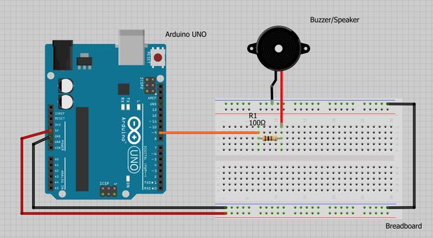
Buzzers work by converting electrical energy into sound through the vibration of a piezoelectric diaphragm. The frequency of the signal determines the tone of the sound produced. To wire a buzzer, connect the positive terminal to a digital output pin on the Arduino and the negative terminal to the ground (GND). For an active buzzer, you can simply turn it on and off using digital signals. For example, you can alternate between HIGH and LOW states to create a beep. A passive buzzer can generate tones of varying frequencies using the Arduino’s tone() function.
The wiring for a simple piezo buzzer can be seen below along with a code snippet. The code will cause the buzzer to continuously start and stop buzzing.
const int buzzer = 9; //buzzer to arduino pin 9

void setup(){
  pinMode(buzzer, OUTPUT); // Set buzzer - pin 9 as an output
}

void loop(){
  tone(buzzer, 1000); // Send 1KHz sound signal...
  delay(1000);        // ...for 1 sec
  noTone(buzzer);     // Stop sound...
  delay(1000);        // ...for 1sec
}
- The Buzzer: Understand the fundamentals of buzzers in Arduino.
- How to Use a Buzzer: Detailed guide on implementing a buzzer.
Servo Motors
A servo motor is a rotary actuator that allows precise control of angular position, speed, and torque. It is widely used in robotics and Arduino projects due to its compact size and ability to move to a specific position within a range. Servo motors are ideal for tasks that require controlled movements, such as steering mechanisms, robotic arms, or pan-tilt camera systems.
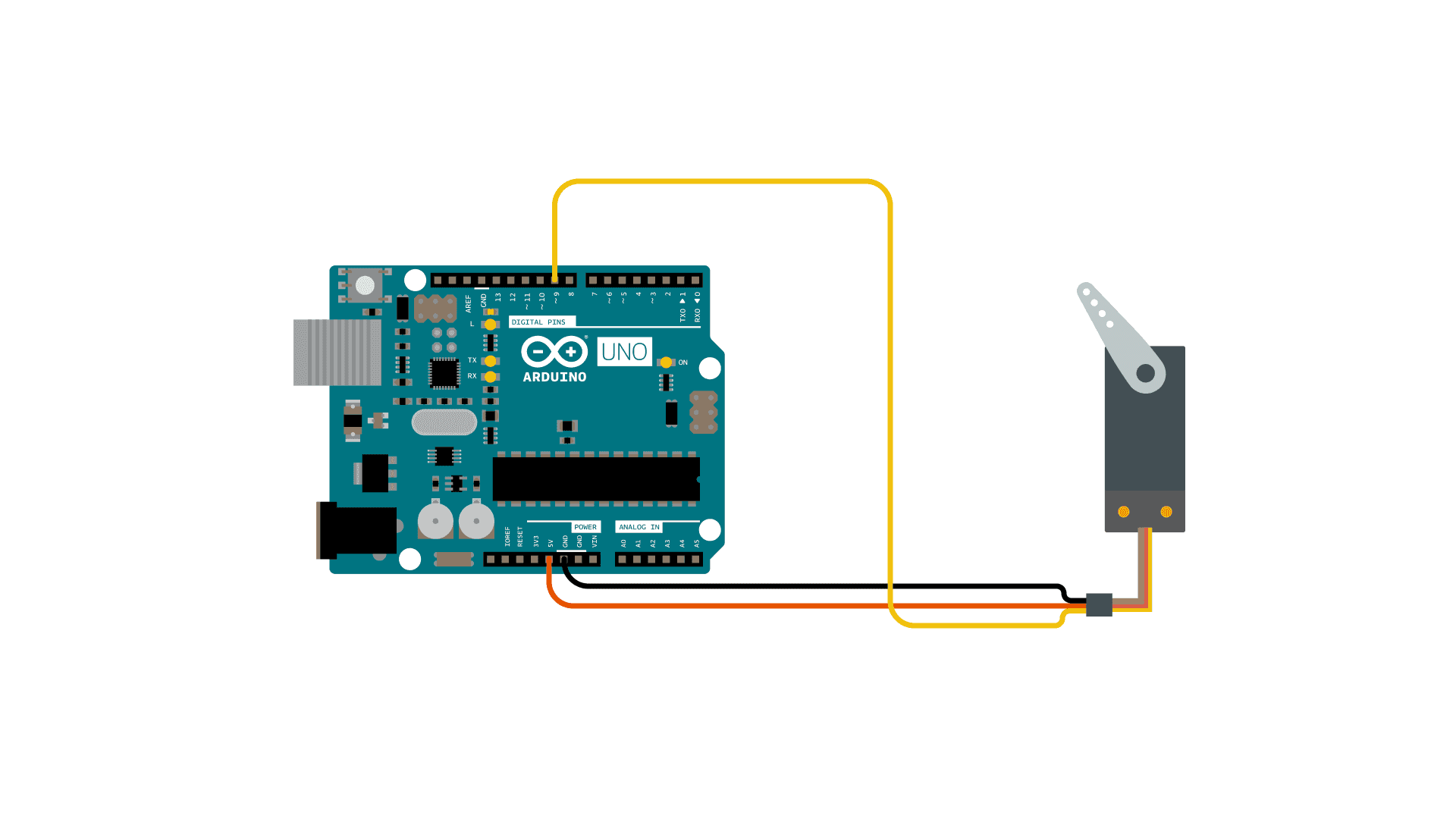
Servo motors typically have three wires: a power wire (usually red), a ground wire (usually black or brown), and a signal wire (often yellow, orange, or white). The power and ground wires connect to the Arduino’s 5V and GND pins, respectively, while the signal wire connects to a digital output pin. The signal wire receives pulse-width modulation (PWM) signals from the Arduino, which dictate the servo’s angle of rotation. Most standard servo motors have a range of motion from 0 to 180 degrees.
A simple wiring of a servo motor setup can be seen below. A code snippet is also below, and this snippet causes the servo motor to rotate back and forth.
#include <Servo.h>

Servo myservo;  // create servo object to control a servo

int pos = 0;    // variable to store the servo position

void setup() {
  myservo.attach(9);  // attaches the servo on pin 9 to the servo object
}

void loop() {
  for (pos = 0; pos <= 180; pos += 1) { // goes from 0 degrees to 180 degrees
    myservo.write(pos);              // tell servo to go to position in variable 'pos'
    delay(15);                       // waits 15ms for the servo to reach the position
  }
  for (pos = 180; pos >= 0; pos -= 1) { // goes from 180 degrees to 0 degrees
    myservo.write(pos);              // tell servo to go to position in variable 'pos'
    delay(15);                       // waits 15ms for the servo to reach the position
  }
}
- Basic Servo Control: Basic understanding of servo control.
- Servo Motors: Resource expanding on the basics of servo motors.
- Servo Library: Documentation for the Arduino Servo library.
Stepper Motors
A stepper motor is a type of DC motor that divides a full rotation into a series of discrete steps, making it ideal for applications requiring precise control of angular or linear position, speed, and acceleration. Unlike servo motors, stepper motors are not limited to a specific range of motion and can rotate continuously in precise increments. This makes them widely used in CNC machines, 3D printers, robotic arms, and other Arduino-based projects.
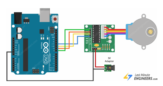
Stepper motors have multiple coils organized in phases, and the motor is driven by energizing these coils in a specific sequence. Most stepper motors have four or more wires that are connected to a motor driver, such as the A4988 or ULN2003, which interfaces with the Arduino. The motor driver controls the sequence of energizing the coils based on signals sent from the Arduino, allowing for smooth and precise movement.
The 28BYJ-48 4-Phase Stepper Motor is the simplest stepper motor that comes with Arduino beginner kits, and its wiring is shown in the diagram below along with a code snippet that rotates the motor clockwise and counter-clockwise at varying speeds.
#include <Stepper.h>

// Defines the number of steps per rotation
const int stepsPerRevolution = 2038;

// Creates an instance of stepper class
// Pins entered in sequence IN1-IN3-IN2-IN4 for proper step sequence
Stepper myStepper = Stepper(stepsPerRevolution, 8, 10, 9, 11);

void setup() {
    // Nothing to do (Stepper Library sets pins as outputs)
}

void loop() {
    // Rotate CW slowly at 5 RPM
    myStepper.setSpeed(5);
    myStepper.step(stepsPerRevolution);
    delay(1000);

    // Rotate CCW quickly at 10 RPM
    myStepper.setSpeed(10);
    myStepper.step(-stepsPerRevolution);
    delay(1000);
}
- Stepper Motors: Detailed tutorial on stepper motor implementation.
- Ultimate Guide to Stepper Motors: Guide to how stepper motors work physically.
- Stepper Library: Documentation for the Arduino Stepper library.
Summary
This page provides an introduction to essential Arduino components, including LEDs, push buttons, potentiometers, buzzers, servo motors, and stepper motors. Each section explains how the component works, how to wire it to an Arduino, and includes example code to demonstrate its use. These components form the foundation of many robotics and electronics projects, offering a range of functionalities from input and output to precise motor control.
See Also
Further Reading
- Arduino Project Handbook by Mark Geddes.
References
- M. Geddes, Arduino Project Handbook: 25 Practical Projects to Get You Started. San Francisco, CA: No Starch Press, 2016.